A schematic symbol consists of the following items :
Symbol Terminals
Symbol terminals act as connection points for electrical wires on schematics. A schematic wire connects one or more symbol terminals to either another symbol terminal or another schematic wire.

Symbol terminal
Symbol References
A symbol reference is a text marker to identify a part.

Symbol Reference (pointed out by red arrow)
Symbol Part Values
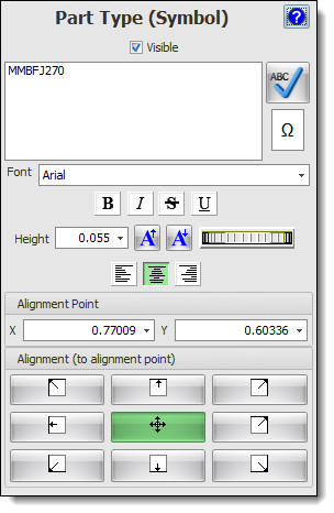
A symbol value is a text marker to identify a part type.

Symbol Value (pointed out by red arrow)
Terminal Magnets
A terminal magnet, shown below, serves as anchor points for symbol terminals.

A symbol using a terminal magnet
Symbol Graphics
To show the functionality of a symbol to the viewer, you need to add graphics that symbolically represent the part.
The Op. Amp graphics shown below are solely for the viewer and represents what the part does: it does not contain any electrical information.

Op. Amp Graphics