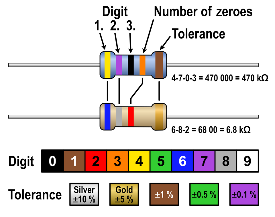
The resistor color code is a system used to indicate the resistance values of resistors.

Resistor Color Codes
Standard resistors use a series of colored bands to indicate their value and tolerance. Here's a breakdown:
Basic Color Codes

Color Codes
•Black- 0
•Brown- 1
•Red- 2
•Orange- 3
•Yellow- 4
•Green- 5
•Blue- 6
•Violet (or Purple)- 7
•Gray- 8
•White- 9
•Multiplier:
•Black- x1
•Brown- x10
•Red- x100
•Orange- x1,000 (or 10^3)
•Yellow- x10,000 (or 10^4)
•Green- x100,000 (or 10^5)
•Blue- x1,000,000 (or 10^6)
•Violet- x10,000,000 (or 10^7)
•Gray- x100,000,000 (or 10^8)
•White- x1,000,000,000 (or 10^9)
•Gold- x0.1
•Silver- x0.01
•Tolerance:
•Brown- ±1%
•Red- ±2%
•Green- ±0.5%
•Blue- ±0.25%
•Violet- ±0.1%
•Gray- ±0.05%
•Gold- ±5%
•Silver- ±10%
•No band- ±20%
For resistors with four bands
•The first two bands indicate the two most significant digits of the resistor's value.
•The third band indicates the multiplier.
•The fourth band indicates tolerance.
For resistors with five bands
•The first three bands represent the three most significant digits.
•The fourth band is the multiplier.
•The fifth band indicates tolerance.
For resistors with six bands
•The first three bands represent the three most significant digits.
•The fourth band is the multiplier.
•The fifth band indicates tolerance.
•The sixth band indicates the temperature coefficient (ppm/°C), which is not always present.
Using these color codes, you can decode the value and tolerance of a resistor by looking at its bands and referring to the above color values.