Parts consist of 3 distinct representation:
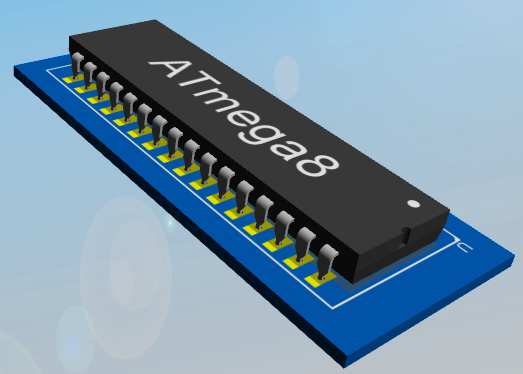
1.The physical device, This is shown in the 3-D view.
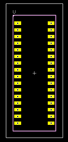
2.The footprint or land pattern which defines how the part is Attached to the PCB using pads, silkscreen graphics, placement points (which serve as device coordinates for pick and place machines) and courtyard rectangles (which define the area used by the part). on the PCB.
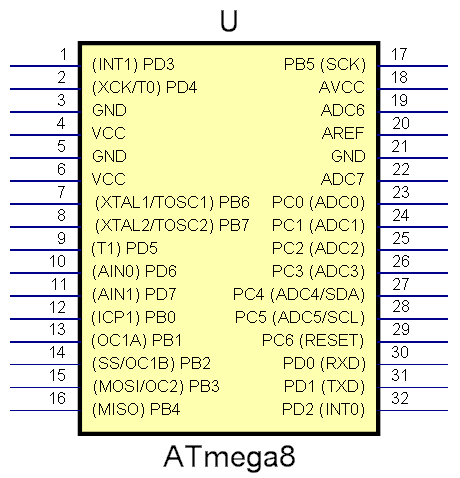
3.The schematic symbol(s). A part can have the logical device split up into more than one symbols. This is common in logic devices that contain more than one logical gate.

The Physical Part (3D)

The PCB Footprint or Land Pattern for the part (2D for PCB layout)

The Schematic Symbol for the part (for schematic diagrams)
You place one or more parts on your schematic(s).